Monday, December 16, 2013

Shop Go Shopping Cart


From time to time the blacksmith shop is presented with an unusual domestic project.  In this instance it was to salvage two broken axels on a Learning Journey Shop and Go Shopping Cart before the granddaughters arrive for their Christmas visits.

This shopping cart has seen a lot of use for five or more years and I made a glue repair a couple of times but this time it was in bad enough shape that more was required.

I removed the wheels and measured for new axels - 9/16” round worked well.  I fabricated a frame from 3/16” x 1” flat bar.  That was the only tricky part because of the odd-angle mitering at the corners so it would fit snugly inside the plastic base perimeter.  3/4” square tube made nice housings for the axels.  Holes for cotter pins were drilled in the ends of the axels.

When I was satisfied with the fit, I cut off the original plastic axels and attached the steel frame to the cart with clear acrylic adhesive and let it harden overnight.  The next day the wheels were mounted and it was ready to go shopping.


I looked up this toy on the web and it is apparently very popular and has been through several versions so there are probably many thousands of them out there somewhere in the world with broken axels.  This is one idea of how to salvage them.
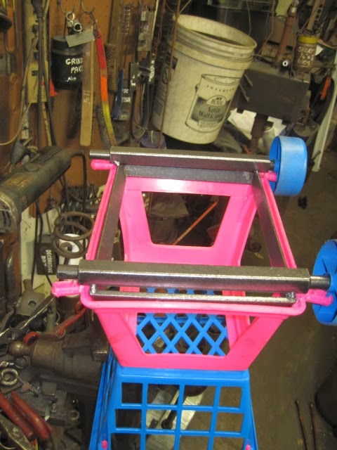
Frame fitted before plastic axel removal.

Assembled with adhesive.

Sunday, December 15, 2013

Cone Mandrel Plans

On 3/2911 I wrote about how I made my first cone mandrel.  This is an update with a SketchUp version of the plans.


The concrete filled base was originally designed to fit a purchased mini cone mandrel.  Subsequently, I’ve used it to hold several other mini cones, a ring roller and just about anything with a tang of appropriate size.

The cone drawn to fit my original mini mandrel.

All components except for a couple of bags of concrete mix.

Saturday, December 14, 2013

The Rivet Buck Helper


I recently made a monogram boot scraper for a client.  He will mount it on a heavy rock of Flint Hills limestone from his property and present it to a friend in Colorado to whom the VA lettering applies.

The client had prepared a sketch which I only slightly modified to suite my construction plans.  The changes were mostly based on strength considerations.

The light surface texturing, rust patina and rivets were added to enhance a rustic appearance.  I like the rust finish color with our limestone rock and it is essentially maintenance free.  The finish was created with my standard hydrochloric acid/hydrogen peroxide treatment, washed, and coated with a quick drying satin polyurethane.  My final sealer coat is something of a “shop secret”, although not a highly guarded one.

There is some hidden interior MIG welding in the construction to make it easier to handle the collection of pieces before drilling the rivet holes.  I only have a helper for a couple of hours a day so we have to work fast to get everything done which needs doing.  In this case I wanted to get all the rivets placed in advance so, when Ken came, I could light the torch and we could finish the peening quickly.


I put the appropriate rivet buck in the vise and built a socket around it and added a support arm.  That allowed me to rest the boot scraper on the support arm and position each rivet hole over the buck.  Then I could insert the 1/4” x 1” rivet and peen it just enough that it couldn’t slip back out.  The plan worked slick as a whistle. 
Rivet buck and set.

Rivet buck helper.

Rivet buck helper in position.

Helper detached from the buck.

The helper at work.

Friday, December 13, 2013

Pottery Kiln Fire Grate


A client brought me drawings of several ironwork projects.  One was a pottery kiln fire grate.  After some discussion, we decided to make it in two sections to make it easier to move.  Also I designed a system which would allow very easy replacement of the grate bars as they burn out.

The legs and front and back rails are at the periphery of the fire and not as likely to burn out as the grate bars.  The bars are upset on each end by peening so they can’t slip out of the rails and the rails lift off when the corner drop pins are removed.


In this case, the design is more fabricating than forging.  The rails were tack welded and the 7/8” holes for the bars were drilled.  Then the tack welds were removed.  In earlier grates I have fullered the holes.  The drop pins are forged from 5/8” round.  The shank is drawn down to 3/8” weak and the head is upset in multiple heats.  The grate bars ends are peened with the help of a vise socket buck.


Client's sketch.
Construction plans with modular design and provision for quick change of grate bars.

Peening of grate bar ends in a vise socket buck.

Thursday, December 12, 2013

Making a Fire Grate


I’ve only made a few fire grates.  My clients haven’t cared much about how they will look and just wanted them simple.  That pretty well makes it a fabrication job.  They haven’t provided much opportunity for forge work and they require a site visit to study the fire box and chart the footprint, etc.  It’s the kind of job I now try to avoid, but I’m glad I learned a little from the experience I have had.

On the first grate I made I used, as I recall, 5/8” square bar and the clients turned out to be serious log burners.  The center part of the grate only lasted a couple of years.  When I built their next one I used larger stock and made the design such that replacing the center grates would be easy.  That became my standard plan.  

My approach was to measure the fire box and draw a sketch and take a couple of photos.  If there was some special feature such as a gas pipe to supply a log lighter it had to be accommodated when deciding where the feet of the fire grate would be placed on the trapezoidal shaped floor.  With the position of the feet recorded on the sketch I could return to the studio and make the two end bridges and set on a layout table just as they would sit in the fire box.  Then, I cut the front and back rails which would support the grate bars.

Then, I would decide whether a center bridge would be needed to support the rails and how many bars would be needed to fill the width with a 3” or so gap between bars and mark those positions on the front rail.  A soapstone line can be drawn on the layout table extending back along the line of each end bridge to a vanishing point.  Then, using a chalk line or a straight edge lined up to the bar positions on the front rail the corresponding positions can be marked on the back rail.

Usually, there were seven to nine bars of varying length, due tot he trapezoidal shape.  Rivets were my favorite for attaching the bars to rails.  They would allow easy removal for grate bar replacement.  In both the bridges and the grate bars the bends were done by making a shallow bandsaw kerf, heating in the coal fire and bending.


Recently I made a grate for a potters kiln using a different design which allows even easier bar replacement.   I’ll get that material together and post it soon.

Site visit sketch.

Improved sketch of foot positions.

Improved sketch of firebox with gas line pipe.

Vanishing point grate bar layout plan.

Drill hole positions for rivets marked.

A flame finial grate assembled.

Wednesday, December 11, 2013

A Good Day at Work


Some years ago, I heard a story that went something like this.  When you’re on your death bed, I’ll bet one thing you won’t say is, “I just wish I could have spent one more day at work.”

I left my “day job” over ten years ago and it is in that context that the above story still rings true.  However, now that I live the artist blacksmith life, I don’t feel the same way, at least in part because what I do now doesn’t seem exactly like work.  I suspect, when he times comes, I’ll wish I could have spent one more day forging in the shop.

I know that I complain too much.  Betty reminds me frequently.  Every day I plan an agenda and it always falls short due to one interruption or another.  I have come around to thinking, I should be working in the shop by 0900 but I know it won’t be until 1100 although when I go to bed I don’t have a clue what obstructions will pop up to delay me two hours.

Occasionally there is the rare day when I get to the shop at 0800 and work.  No errands, No home chores.  That’s one kind of day I’ll wish I could repeat just once more.  Today was another day I might want to repeat.  I got to the studio about 1000 after making a blog post and preparing some images for a client and organizing them in a email Betty will send later.  Also there was a phone conversation with one of my sons about some property he is considering buying.  First there was clearing out the contents of the tumbler and putting each piece where it will next be worked.  Then there was some work modifying dies I concluded were not quite right.  Next was the repair of a Granddaughters plastic pink and blue toy shopping cart which could only be salvaged by adding some steel framing.  It looks like my plan will work well - I’ll have a good idea tomorrow when the parts come out of the tumbler ready for final assembly.  Yet, I won’t know for sure until it passes the Granddaughter approval test.  The final project was fixing the wheels on Betty’s hose cart. That has been on my “To Do” list since April.  Today, I checked it off.


Yes.  Today was a day I might like to live again.  Tomorrow I plan to write about how I make fire grates.

Tuesday, December 10, 2013

True, Strong and Weak


Several years ago I helped one of my sons install siding on his new home addition.  He ran a framing business and his main helper was also a carpenter.  The took turns measuring and cutting lengths of siding boards.  It was interesting to see how quickly and efficiently they worked.  Right away I noticed something unfamiliar to me in their conversation.  The person measuring would call to the person using the sliding miter saw the length to be cut.  I heard terms such as “Six foot, four and a quarter weak.” Or, “Seven foot, two and five-eights strong.”

I don’t think I ever discussed it with them but it impressed me enough that I remembered it and started using the terms as I did measuring.  It is easier to read the tape to the nearest eighth inch mark and use strong or weak to signify which sixteenth is the cut line.  I suppose another pair of modifier terms such as short/long or shy/proud could be used too.

I use this method almost every day when working with the power hammer.  A lot of forging is done to a particular dimension so I have a set of stop dies which range from 14 gauge, 0.0747”, (I had to look that up), to 1.5”.  Even though the stops are made from some sort of tool steel, over time they thin.  When that becomes noticeable the stops is designated as “weak.”

For instance, a 3/8” stop will become 23/64” in thickness after some use. When it becomes visually noticeable the die is labeled “3/8” weak.”  After further use the stop will thin to 21/64” and that is closer to 5/16” than 3/8” so it should now be designated as “5/16” strong.”

For my work, that difference doesn’t often make a practical difference.   Close is good enough in horseshoes, hand grenades and most of my forging.

Thinning of the working depth.

Label of thinned stop. 
Stop selection for a forging session.