Showing posts with label fly press. Show all posts

Wednesday, March 5, 2014

Fly Press Work Station


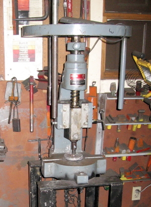
Recently I’ve been using the fly press quite a bit and doing some reorganizing of tools and making improvements.  There is one thing I wish I had done differently and could still change.

I probably should have made a triangular base or set my rectangular one on-the-diamond.  I do most of my work seated and that way it would be easier to straddle the base.  Otherwise, I haven’t had any problems with the way I constructed it.  It is fairly light weight in itself but I set a 5  gallon bucket inside and filled it with sand and I also store some heavy steel blocks and lead blocks there to add mass.  Without the added bottom weight the setup would be rather top heavy.  The weight additions are modular so they aren’t awkward permanent fixtures.

The rotational force applied when operating tends to make the press turn on the floor in a clockwise direction.  That was easily solved by adding a flange to the right front foot with a center hole.  I drilled a corresponding hole in the concrete with a masonry bit and made a drop pin to insert and block the movement.  Nothing more was required.

I welded a piece of round rod to the lower right ram guide bolt to serve as a handle.  When I run the ram up to change dies I give this a quick turn to lock the ram in place then loosen it when ready for use again.

I made a dedicated wrench for the ram tool holder bolt by welding a T handle on a socket wrench and attaching it to the table with a cord so it was always available without searching.  I did the same thing with a small ball peen hammer which I occasionally use to knock something loose or make an adjustment.  I also keep a tweaker blade close by for this or that.

I try to remember to leave the press set up for either bending or center punching when I’m not working on a fly press project.  That way it is always available as a somewhat generic shop tool.


I didn’t count but probably have made about 50 tools to fit the machine over the years and now rarely need anything new.

Early Fly Press Setup 
Tool rack and tray added 
Fly press area mess before I recently cleaned up

Ram lock, corded tool holder wrench and ball peen, tweaker

Stand with weight box and drop pin foot flange

Wednesday, February 12, 2014

Smithing Magician in the Fly Press


When I bought my fly press I could only afford the smallest size.  It has been satisfactory for just about everything except but one.   The ram-to-base clearance was not quite enough to allow me to fit my Smithing Magician tool in the space.  I could have made a smaller version of the SM as one solution but I chose to cut about 3/4” off the upper end of the top dies.  I figured I could always weld back the length if I needed it.  This gives me just enough working distance to do the small jobs I’m planning, mostly some pipe fullering and some sheet veining.

I wanted to use the hex bolt which locks the top tool in the ram as the top die lifting hook so I had to make a top pusher (hammer) tool which extends forward enough to strike the die and still keep the link wire aligned.  I also welded a 3/8” lock washer onto the front face of the top die to attach the wire loop.


I don’t know how satisfactory this will be over time but the learning curve has to begin somewhere.  I may also try a rubber band in place of the wire.

Die hammered down

Die lifted to maximum opening

A careful observer may notice the little relief ground out of the bottom frame in the center.  I did that because occasionally the bottom die would get stuck.  The little slot allows me to slip in a chisel and lift the die free.  Normally the smithing magician is bolted to a base which fits in the treadle hammer and allows me to position both depth and height stops.  It is about 3/8” thick plate and I have to remove it to use the tool in the fly press.

Sunday, February 9, 2014

Fly Press Tool Rack


I needed to test a couple of things with the fly press and couldn’t quickly find the tool I needed.  The reason?  It was somewhere in a pile on the shelf and not in the rack.

These days I’m paying more attention to why some things don’t work well.  This is a great example.  I made the rack when I had made only a few fly press tools like a center punch, slitting chisel, small ball punch, etc.  Later I changed the way I made the tools and developed a standard method of building them.  I wrote about that in March 2011. http://persimmonforge.blogspot.com/2011/03/making-fly-press-tool-tangs.html

After that the width of the hex head of a 1” bolt or the width of a 1” nut was the parameter which determined the width of the tool.  The spacing of sockets in a rack would have to accommodate that width for the tools to store nicely.  I had made the sockets too close together so only about half of them were useable.  When the number of tools exceeded the number of useable sockets the pile began.  

I had not anticipated the design change so I couldn’t very well plan ahead.  And when I made the design change I didn’t plan again.  It would take more time than I have right now to fix the problem but I decided to sketch out a solution in case I ever get around to it.  This is my proposal.  I’d make the socket from short sections of 1.25” square tube just like in the original version.  I would make some small separating blocks of, perhaps, 3/8” square bar.  I’d make a test piece and check the actual spacing to be sure.  I would weld them to a backing bar, perhaps 3/16” x 1.5” flat bar, which would leave the bottoms of the sockets open.  I'd also check to confirm how much standoff was needed from whatever the rack would be attached.

In the meantime I used the cutting torch to cut away part of the hex width so more sockets could be filled.  This type of inelegant solution annoys me, but it is quick and I have plenty of examples of such.


Sunday, September 22, 2013

Fly Press Handles


My fly press came with a single handle.  It’s the one shown in the foreground of the image “All Three Handles.”  It didn’t take long to start thinking about modifications to bettert suit my specific needs.

First was a grip issue.  The end of the round bar handle rubbed uncomfortably on my palm, so I welded on a steel sphere and eliminated that problem.

Next, I noticed that the handle had a tendency to unscrew from the threaded socket in the wheel, so I welded on a piece of thread rod and added a lock washer.

The single handle never seemed to be in the most convenient of the three sockets, so I added two more handles with slightly different design.  This has worked well for me and I haven’t made any changes in several years.

For one job I did make an adjustable handle that mounted on the handle which was closest to being in the optimal position.  It could be rotated and locked with a T-handle in the perfect spot.  It adds length to the edge-to-center distance and increases leverage too.


Tuesday, September 10, 2013

Fly Press Leather Pad Cutter


I make a lot of botanical sculptures mostly of sizes which serve as table displays.  Invariably the heavy base has some undesirable rough areas which could damage a table top.  First, I tried some commercial soft pads with adhesive backs but later moved to making my own pads from cowhide scrap leather.  

Our local farm and ranch supply store usually has a selection of packets of leather scrap.  I look for ones which have flat pieced - preferably black and also long strips, usually dark brown which are good for suspending forged dinner bells.

I cut circles from the flat scrap and fix three pads to each sculpture using black silicone caulk as the adhesive.  I position the pads so they avoid the touchmark areas and make the piece stable.

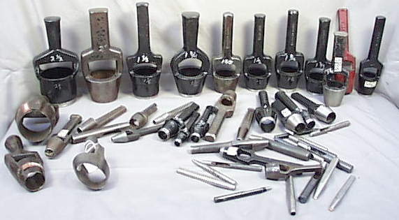
I I could have found a nice cutter in an antique shop I probably would have picked one up.  This site shows a nice collection.  http://www.antiqbuyer.com/images/ARCHIVE_PICS/archivetools/Leather/leathercuts/leather_cutters.jpg  I think those are designed to be struck with a mallet.

Well, I wasn’t that lucky so I made three versions with similar mechanical design but which cut three different size circles and fit in my fly press.  The smallest makes about 1” circles and the largest cuts about 1.5” circles.  I used SketchUp to draw a rough version of the largest one.  

I start the construction process by cutting a piece of lawnmower blade scrap to make the blades.  A strip an inch wide and about 5” long will make the large size cutter.  I forge a circle over a round mandrel and MIG weld the seam and clean up the inside of the blade so it is smooth and won’t have burrs which tend to grab the leather drops and keep them from ejecting.

The blade edge is made by ordinary grinding, sanding and polishing.  I make a cutout in one side of the blade to allow the ejecting lever room to travel and it might be a good idea to cut another knockout access window in case a real jam occurs.

I make a barrel and axle mechanism with some small pipe and round rod.  The ejection lever tip is heated and bent and polished so the angle is optimal for pushing out the cut pads.  

The top structure begins with the 1” x 1.5” bolt which I use as my standard ram tang.  I’ll grind away the threads at the tangent where I want the locking bolt to seat after I know exactly where that will work best.

The shank is cobbled together so it is appropriately long and strong.  In this case I used a large punch drop and a short piece of 1” round and MIG welded it all together.  I usually just “tack and test” before I do the final welding.

The final piece is the bottom tool which will stop the blade travel.  I tried several materials and settled on a block of very high density polyethylene.  I wanted it to stay in register with the blade so I used the black silicone again to glue on a 7/8” nut which exactly fits the fly press base tang hole.  The poly block is rigid enough to back up the leather so a clean cut can be made in three easy bumps and prevents damage to the blade edge.  The more the system is used the better it all works. Some lubrication inside the blade may help too.

The depth is sufficient to cut three pads before ejecting but it is a little harder and probably doesn’t save time.  I should note that the images show the large cutter with the original 60d nail lever.  I later changed that to 3/8” round rod about 6” long.

There are a lot of blacksmiths around demonstrating how to draw a taper or forge and upset square corner so I tend to concentrate on sharing the odd-ball things that are part of my blacksmithing business.  These leather pads are a little detail that can keep clients happy.


I posted the drawing on 3D Warehouse.


Friday, September 6, 2013

Hammer, Bump & Squeeze


The most powerful tools in the studio are the power hammers, the hydraulic forging press and the fly press.  Each has a distinctly different way of delivering force which is very helpfull in different circumstances.

I recall Abraham Maslow’s, “If all you have is a hammer, everything looks like a nail.” http://en.wikipedia.org/wiki/Law_of_the_instrument  I became acutely aware the the differences when I really became interested in die making.  

The fly press is a precision instrument which can make detail very well and is easily hand controlled because it is a slow operation.  It’s down side compared to the two other big tools is that it is less powerful.

The hydraulic forging press produces a squeeze without any bounce, but, because it is slow it can’t coin as well as the power hammer.

The power hammer is best for coining but because it has some bounce it is not as easy to control as the other two.

When the only big tool I had was the power hammer every die was designed to work with it.  After I built the forging press I could immediately see I needed to make some changes and move to a progressive die strategy where some preforming mass was done with the press so the coining finish work would be easier on the power hammer.  It has taken a couple of years to get this nearly perfected and it has been very helpful in extending design options.

In almost every project I try to get as far as I can with the power tools before I have to resort to hammer on anvil.  It is in some ways the most intimate and pleasurable phase - the finishing - but it is also the part which is hardest on my old frame.

I’ve often said, “My work determine my tools and my tools determine my work.”  In this circular process my work has evolved to use a lot of dies.  I have perhaps a couple of hundred which I have made to do very specific processes.  I’ve learned a lot how to make these dies as I climbed the learning curve. I’m thinking that I should try to pass on some things I discovered which helped make the process better and easier. Last September, I posted an introduction to the subject.  http://persimmonforge.blogspot.com/2012/09/introduction-to-blacksmithing-dies.html  Now, I’m planning to move on from there with some further details and illustrations.  Probably, it will be somewhat jumbled as I don’t have enough time to get it better organized now.  I’ll try to explarin how each of my power tools related to my die making proceedures.  We’ll see how it works out.


Friday, September 7, 2012

Fly Press Handle Modification


My press came with a single handle.  I have found that three handles work better for me.  I fabricated the additional two handles from a short piece of 1” thread rod welded to about a foot of 1” pipe.

I still didn’t like the tendency of the handles to work loose in the threaded sockets of the fly wheel so I welded a bolt extension to the top which allowed me to attach a jam nut with lock washer.

I also found that adding a 2” ball to the handle bottom end made operation much easier on the hands.

These are all small things but everything that makes the day go easier I appreciate.


Monday, May 30, 2011

The Pivot/Lock Rod Fuller


Yesterday I needed to make several pieces which I call "pivot/lock rods". They require a pair of opposing fuller marks to demarcate where to begin drawing each end segment on a piece of flat bar. It has been several years since I last made them and don't recall exactly how I it was done as my record keeping wasn't as good back then.

I decided it would be easiest to do on the fly press where I could sit down and get a really good view of of the register of the work piece on the bottom fuller while spinning down the top fuller. The work needs to be rather precise. The only problem was that I hadn't yet made a pair of fullers of the appropriate radius. All the completed ones were larger.

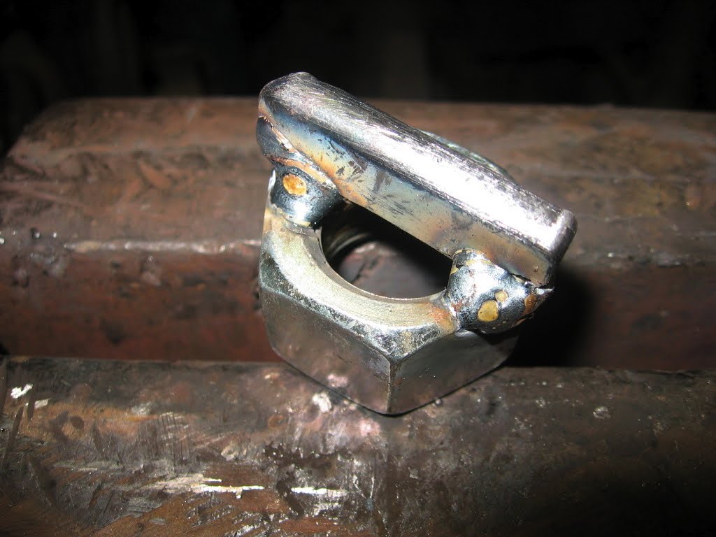
The decision was to go ahead and take the half hour or so which would be required and make this tool. Step one is see in image 01 showing a piece of 5/16" radius H13 tacked to a 7/8" nut which works perfectly as a bottom tang.

Step two is see in image 02 where I selected a 1" x 1.5" bolt as the top tang and welded a short shaft which I measured when I had the bottom tool seated. The top 5/16" radius H13 piece was tacked to the shaft.

I seated the top tool in the socket and tightened the locking nut with the rotation in the position for general use (avoiding obstruction). The end of the nut slightly flattened two of the screw threads on the top tang which were easily seen when I removed it. I used the grinder to cut away those threads so the lock bolt would rest on a flat surface in that location.

Image 03 shows all pieces lined up and tacked with two bottom flanges added to take stress away from the welds between the H13 and the nut.

The final step was to MIG weld all around and add a short handle to the bottom tool to make it easy to rotate into exact alignment with the top tool which is locked.

It did take about 30 minutes to make the tools but it only took a couple of minutes to mark the six work pieces perfectly and the tools will be available for other jobs now.

The Smithing Magician http://www.britishblades.com/forums/showthread.php?17493-Smithing-Magician-Guillotine would be my next best choice for this job. I have it set up for the treadle hammer and the light in that workspace isn't as good as at the fly press and my angle of view is also not as favorable. I could have placed the Smithing Magician in a vise and struck with a hand hammer

Actually there are quite a few ways to skin this cat but mostly I wanted to show a quick way to make fly press dies.

Sunday, March 20, 2011

Making Fly Press Tool Tangs


Following up on the theme of making edge tools with tool steel these are some ideas about making the tangs with which they will mount in the fly press.

My fly press is a small one but just right for my purposes - the Goldilocks Principal. The socket in the ram which seats the top tools has a 1" diameter. Depending upon the required finished length of the tool I use either 1" x 1.5" bolts (shorter tools) or 1" thread rod (long tools).

The tang needs to seat as deep as possible to provide the lateral support but it should not be able to bottom out and upset the end of the tang or damage the base of the socket. All the vertical force on the top tool should bear broadly on the face of the ram. When using the thread rod I use a depth gauge made from a piece of tube which fits over the 1" rod. A 1" - 8 nut is screwed down to expose just the right length of tang and then welded in place with the MIG welder.

If I need 60º Indexing, 5/8” - 11 coupler nuts work great as top tangs. Usually the tool fits in only one or two rotational positions so I just grind a flat spot to the depth of the threads so the set screw will have a point to seat nicely in those positions.

The tangs for the base socket are made from 7/8" - 9 nuts if a slightly loose fit is tolerable or a 1" section of 1.5" schedule 40 pipe with a 1/8" slit cut out when a tight fit is required. There are 1/2" slots in the base frame on both sides of the bottom socket so "outrigger" bars can be attached to the bottom tang and extend out to drop into one or both of those slots to securely fix the rotational position of the bottom tool if needed.

When attaching a tool to the top tang, such as was described in the previous post, I allow for a standoff gap and make a single tack which permits me to double check and adjust the orientation before final welding.

It seems important to pay careful attention to the condition of the set screw in the ram. I replaced the original one with a grade 8 bolt and made a custom wrench from a socket wrench with a welded "T"-handle and it hangs on a cord from the stand close at hand. Inspecting the tangs for any fret marks from the screw may show there is undesirable movement of the tang which could damage the screw. If the end of the screw became upset or the end threads damaged it could be very difficult to remove the screw without damaging the threads in the ram. As usual it is easier to prevent a problem than fix one.

Using Tool Steel


Yesterday I forged a slitting chisel and an opening chisel for the fly press for a future project. I chose H-13 tool steel for the job. The only alloys I buy are H-13 and S-7. From time to time there are opportunities to pick up free of charge some used trenching bits for hardy tool blanks or some coil spring or a torsion bar but I don't buy them. Years ago I placed a couple of orders from a major supplier and paid the premium price but in recent years I have always been able to find what I need at a tailgate sale for a very reasonable price.

I picked a 1" round bar of H-13, heated it in the coal forge and forged the shape of each chisel in a single heat on the power hammer. The rest of the work was done with the bench grinder, flap disc and belt sander, silicon carbide wheel and finished with the hard felt wheel dressed with chromium oxide polishing compound.

I welded it to the fly press top tang in proper alignment. I first tacked it in one edge spot with the MIG welder with a short bead which I can bend cold while the tool is in the fly press adjusting it's position before the final welding. When it was finished I heated it up above critical and let it air cool.

The tool steel probably cost $2 and it took about a half hour to complete. The process is really so quick and economical it is reasonable to plan on making exactly the right tool for each job.

That leads to the issue of dedicating tools. I have a number of items I make time and again so it seems easiest to dedicate the small tools, jigs, blanks, etc. and store them together until the next time I need them. If I know the tools will be used infrequently for short runs that leans me toward using my "free" tool steel for the edge tools. Many don't need any heat treatment but occasionally one needs an oil quench to harden enough. For the swage type tools water quenched mild steel works well in most cases.

For completeness I should add that I did buy some 4140 annealed die stock for my Smithin Magician and have made several custom dies. The instructions for heat treating came with the material and are as follows.
Normalizing: Heat to 1600/1650°F (871/899°C), hold for 10 min. and air cool.

Annealing: Heat to 1550/1600°F (843/871°C), pack in lime or wood ashses until cool.

Hardening: Heat to 1550/1600°F (843/871°C), and oil quench.

Tempering: After hardening, heat to a temperature 400°F to 500°F and air cool.
I'm sure that's really useful to anyone who has a heat treating oven but I don't. The dies I've made have enough radius on the edge that hardening hasn't been much of an issue so just heating and oil quenching by guessing has worked OK. Some call that the SWAG method, the educated guess, intuition or just guerrilla metallurgy.

Tuesday, March 15, 2011

Finding a Niche


When I became interested in blacksmithing and started my first first forging efforts I had no sense of direction to the work. I was only interested in acquiring capability in general. As time went on and I accomplished more work I continued to cast a wide net and attempted to make many different things. Eventually I could make a lot of things but none really well.

This wasn't a bad strategy for a beginner in my situation where there was no living-breathing instructor, only books. Progress depends mostly on practice, anyway, I think. My further experience path was directed by the specific projects which clients requested. Some proved more satisfying than others and I started narrowing the vision of which things I wanted to do and which I didn't. By concentrating on the most interesting types of work I improved my skill in those areas and the overall satisfaction of the creativity increased.

Large architectural work is not for me. I mostly work alone and don't have the strength of youth and endurance necessary for heavy projects. I prefer smaller projects involving natural forms particularly botanical elements. I incorporate many different kinds of them into various sculptural decorations.

Currently I'm working three projects which employ forging and fabricating hollow forming techniques which I have developed over the years and enjoy using. One is a large sunflower sculpture which will hang on the outside west wall of my studio. The second is a large pair of interior doors which present a woodland scene. And the third is three runs of grape vine hand rail. All include stem, trunk and vine elements up to 3" round. Obviously, solid stock can't work in those applications because the weight would be enormous. I have encountered this design problem many times and find the hollow forming an ideal solution. The closed shape lends great strength with little actual mass.

I can briefly describe the process as follows. Mostly I use 14 gauge HRS sheet but sometimes 18 gauge if even lighter weight is required. I request the steel supplier shear the 14 gauge into pieces 2' to 3' in length and about 4" in width. This size is easy to work given the tools I use.

The first step is to run all the sheet through the coal forge to fire scale and anneal. Next I run the stock through the tumbler with steel aggregate for about 20 minutes. This knocks off all the scale and leaves the surface with a very fine pitted and planished texture which will eventually be the "tooth" which holds the finish in place.

The second step is to heat the sheets again in the coal fire and boldly texture the surface with one of a number of bottom dies I have made for the power hammers which produce specific bark patterns.

Next, I use the flypress with a bottom trough die and top ball die to bend the sheet into the desired radius of concavity needed for the fabrication of the final form. If the sheet is 4" wide and the final form is a branch about 1.25" in diameter (4/pi) I can completely close the tube by switching the top ball die to a top trough die. I don't strive to create a symmetrical pipe as some undulation will be desirable in the finished product.

Finally I place the tube in the post vise and close the seam with a MIG weld bead then fuse the seam with the oxy-acetylene torch and run the finished piece through the tumbler again.

The final structure will require some tapers and bends rather than just single diameter tubes. Tapers are formed by cutting the sheets into elongated trapezoids which are then tubed. Bends can be complicated but often require removing and replacing various geometrical areas.

I find this building process fascinating and I am happy that I have found this niche technique. To each his own.

Monday, November 2, 2009

Forge Room


Continuing a welcoming introduction I’ll present an overview of my workspace starting with the forge room.

The building is approximately 40’x40’ and located about 100 feet from my home - real handy! Located on the north edge of town just a few hundred feet from the Neosho River and just a bit higher than it’s flood plain. To the east, south and west is residential property.

The studio has three first floor rooms and a porch. There is a loft area upstairs. Each space is organized into several dedicated “work stations.”

The forge room is the northwest quarter of the space. When I can’t have the whole studio open due to summer heat or winter cold I can close the doors to the forge
area and leave the heat or AC working in the rest of the studio.

In the NW corner of the forge room is a stationary coal forge with a 3’x3’ apron around the firepot. An electric Champion blower is attached to one side (the motor is
outdoors on the porch so I don’t have to hear that noise) and a Champion hand crank blower on the other side. I can flip a switch and run the big blower and close a blast gate on the hand crank side or slide open the blast gate and turn a hand wheel valve and shut off the electric blower side. I feel this gives me the best of both worlds -
the hands-off advantage of electricity or the hands-onfine control of the hand crank.

Beside the coal forge is my four-burner, loose brick gas forge hooked to a 100 pound propane tank outdoors on the porch by a quick connect coupler. It is on wheels and I can choose between using one, two or four burners. Above it is a large hood and exhaust fan. A two-burner forge and a three-burner, both portable with 20 pound tanks are on the north porch along with the coal supply.

In the NE corner is a 50 lb late model Little Giant power hammer. On the east wall is a work bench. I hang the power hammer dies on a pegboard above it. A carbon monoxide monitor is plugged in there.

To the left of the power hammer is a stationary 40 gallon quench tub, a cone anvil, a large swage block on a low stand both of which get moved front and center only when I need them.

To the right of the workbench is a small swage block on a tall stand. On the wall above this is a large paper pad, charcoal & chalk holders and slate chalk board.
This is where I sketch conceptual drawings as I work.

In the SE corner is a fire extinguisher small rolling work table and the flypress. On the wall is my “sketches in iron” display where I store small test pieces - a library
of “visual solutions.”

On the south wall is a shop built Hossfeld-type bender, a 6” pedestal grinder, a Smithing-Magician, and a tall industrial fan.

In the SW corner is my inline treadle hammer and alphanumeric stamps and touchmarks and other associated tools.

On the west wall next to the coal forge is a 4’ work table made from 15” channel mounted on a scraped lathe base.

In the center of the room is a 5” post vise on a large stump, a 4” post vise on a 14” stump, a 120 lb Peter Wright anvil mounted on a concrete-filled beer keg and a 250 lb
Trenton anvil mounted on a large stump.

The next installment is the Layout Room.