Tuesday, February 26, 2013

Dental Checkup for Tongs


Last summer I took apart several pairs of old tongs which needed repair or reshaping to be useful but without time to go further I put them in a bucket and moved on.  Recently I came across another pair of tongs needing repair and decided to tackle all of them in one bite.  Bite seems like an appropriate word since it is mostly the bits that need attention.  I did a quick “dental checkup” on some other ones I use a lot and added a few more to the pile.

As I worked I really studied what I liked or didn’t about the mechanics of each one and tried to find the best way to describe those features so I would be more aware of what was really working for me.  There is a paradox in hand tool function.  If the tool is working perfectly, it is almost invisible.  It seems a natural extension of the hand - not something seeking attention.

So that led me to refining my tong vocabulary and being more specific about how I thought about their anatomy.  There seems to be quite a bid of variation in how blacksmiths describe tong parts and styles so what works for me isn’t going to necessarily appeal to others but here goes.

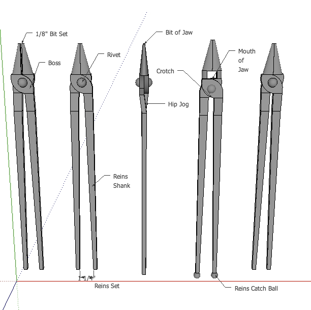
I think of tongs as having four general zones; the reins, the boss, the rivet  and the jaw.  The reins to tong length ratio determines to a large part the force which can be applied.  A boss, in general is a protuberance or enlarged area of a shaft.  In this case it is the hinge plate for the fulcrum - the rivet.  

The portion forward of the boss is the jaw.  The jaw has two divisions; the bit at the tip which usually has a specific shaped opening when viewed down the long axis.  The bit is often about an inch in length.  The gap between the pair of bits is the “set” of the jaw.  The rest of the jaw leading into the boss is the mouth area providing what ever space is needed for the object grasped.  Bolt tongs have a cavity to accommodate the bolt head.  The mouth can be in straight alignment with the long axis, offset, or considerably offset - goosenecked.

The boss area largely controls any wobble tendency and gets the brunt of the frictional wear.  Using a relatively large rivet, 3/8” to 1/2” diameter, and making the hinge plate an inch or more in width provides a lot of mechanical stability.

The gap between the reins where they join the boss is the crotch.  I like that to be about 1/2” so the tongs hang nicely on a bar rack.  That gap is the “set” of the reins.  The inch or two run coming off the boss is the hip area and this is where the jog of the reins occurs to bring them into parallel with the long axis.  The long run of the reins is the shaft and the terminal area is the catch region.  An actual catch may be absent, a short terminal jog away from the long axis or some actual mass such as a ball.  Sometimes it is a ring on one rein which flips over and catches on the other to act like a tong clip.

So that is the terminology I used as I went through the repair process.    I made a number of observations related to the mechanics and about the specifics of bit design which I’ll post later after I’ve had more time to make more sketches for illustration.  Later still, I plan to do a segment on tong making.

Back to work - living the dream.

http://www.persimmonforge.com/

Wednesday, February 20, 2013

Making a Nail Header


Yesterday I had to start making some large square nails for a display.  The plan was to cut stock blanks of 3/8” square bar cut in 4” lengths.  I would first upset the head a bit then draw a square point on the anvil.  Then draw the shaft to 5/16” square on the power hammer.  The head would be finished using a hand held header over the hardy hole.

A quick check revealed that my nail headers were all dedicated to smaller stock so the first step would actually be to make a header.  I selected a working length bar of 1” square hot rolled.  I drilled a 1/4” pilot hole, centered about 3/4” from the end.  The bar end was brought it to a high heat in the coal fire and the hole opened with a blunt bullet punch on the HFP using a grease with coal dust lubrication.

With another hight heat I used a handled square punch and hand sledge over the hardy hole and punched the square hole.  After checking to make sure the opening was the proper size I drew out the handle in two more heats.  

Final dressing was done with the pedestal grinder, angle grinder and file. The tool was heated again and water quenched. Being mild steel it won’t get much harder but it will probably be fine for the planned short run. If it shows signs otherwise, I’ll case harden it.

This morning I made a sketch and posted it to the 3D Warehouse.


Saturday, February 9, 2013

Sharing with 3D Warehouse


Yesterday I decided to figure out how to share files on the Trimble 3D Warehouse (powered by Google). http://www.sketchup.com/product/3dwh.html

I have frequently searched their archive for models to help me illustrate ideas so I wanted to try and give some pay back by posting a few visualizations I’ve worked out.  I added two versions of my treadle torch and one file of my platen table. 


I think I followed the instructions carefully but I’m not sure that one of the items is correct -  “In SketchUp, hide your lines and profiles for a cleaner screenshot. View -> Edge Style -> uncheck Display edges and Profiles.”

When I downloaded my files to see how they worked I had to check the Edges and Profiles again to make them look the way I like but I’ve noticed when I’ve down loaded other files they usually arrive with Edges and Profiles already checked.

Experience is a good teacher so I’ll keep experimenting and anticipate that I’ll soon understand the process better.  It took me a couple of years of use to become really fluent with SketchUp but it has been well worth it for me.  Using the axiom that “a picture is worth a thousand words”, has paid off when illustrating ideas for clients and with other types of design work.

For those who are not familiar with SketchUp is may seem a bit intimidating at first.  One way to get started is to visit the 3D Warehouse and do a search for “forged” and study the results.  After a while they will get the hang of modifying the searches to more specifically find illustrations.  This is an example of a nice swage block.


Friday, January 25, 2013

Pedal Hammer Seat Bracket Modification


I have been working on some small botanical elements, grape leaves, sunflower centers and such using the pedal hammer and veining tools.  The machine I use frequently is a prototype model and had a old style seat bracket which didn’t allow enough foot clearance when sitting down and getting up.  Every time I sat down and wiggled my left foot through the narrow space I would think, “I should fix that.”  However, that thought was immediately followed by, “That will take thirty minutes and be a hassle.”  So the problem lingered until yesterday.
I finally got an adjustable wrench and took the seat and bracket off, made two cuts and two welds and put it back on in thirty minutes.  A big improvement.  So the lesson, for me, is when building the bracket try to keep a shoe length distance between the anvil post and the seat bracket frame.
Now every time I sit down I’ll think, “I should have done that two years ago.”


Treadle Torch Followup


Imagine what a surprise it was to open the January/February Issue of NOMMA’s Fabricator and see the article “Hot Treadle Torch” by “Uncle Bob “ Walsh just after I had written about rebuilding mine.

As I thought about what seemed like a coincidence I decided that there may be less serendipity involved than I first thought because I had recently been reading the articles in the fabricator he had been writing about making acanthus leaves.  That may have started me on the track of reworking my treadle torch.

He mentions that he saw Wendell Broussard use a treadle torch at an ABANA demonstration.  I wonder if it was the same occasion in La Crosse, Wisconsin when I watched Wendell for my second time.

I posted a couple of pictures of Wendell’s work then.

The Fabricator article is well worth reading.  Also, his explanation of the pros and cons of gas and coal forges is well done.

I did notice the system described is a bit different from mine.  First, I do use acetylene and oxygen and don’t have a soot problem if I keep the pilot light flame carefully adjusted. And secondly, I don’t generally use the rosebud tip but use  a cutting tip instead because my setup is used more often in the free hand torch mode than the treadle mode.  I, too, use the quick couplers and the Smith company gas saver and believe they work well.

I found a few more images of Wendell's work from the 2002 conference.


Friday, January 18, 2013

Treadle Torch Plans


A year ago I wrote about using a gas saver with the torch.  I intended to post a set of plans showing how I made mine but never got that done.  Then I thought about rebuilding mine because it had some problems so I started making some sketches to see if I could find some improvements.


The first decision involved whether the setup would be fully dedicated to treadle operation or would it also accommodate freehand torch use. I chose the latter as that is the way it has worked out to be most useful in my shop.

In this dual setup the torch is designed to hang from the shutoff lever of the gas saver when in freehand mode and to hang from a hanger fixed near the pilot light when in treadle mode.  A weight is hung on the gas saver shutoff lever when in the treadle mode.  The weight is enough to power shutoff but still easy to lift with toe pressure on the pedal.

The next decision is whether to place the torch tip near the gas saver pilot as factory built or to move the position of the pilot light by adding a copper tube extension.  I decided to adapt to the pilot on the devise without alteration other than add a hose clamp handle to make adjusting the pilot flame easier.

After I checked a couple of references on the internet


and aided by my previous experience I started building from the ground up. I decided my comfortable working height was about 44” in the treadle mode.  I was satisfied with the stability and maneuverability of the plow disc base on my current setup so I started with another 16” disc.

Next the Primary Post was welded to the center of the disc in true vertical position.  After that I worked out a pedal-lift mechanism with about 2” of upward travel and the work height adjustment.  That proved that there needed to be the additional 1” space between the primary post and the lift sleeve for the base articulation. 

After that portion of the frame was welded the upper structure was built. First I mounted the Gas Saver to a platform which would be removable if I wanted to use it in another location from time to time.  I welded the two arms of the fixed bracket to the Gas Saver adjustment socket and clamped it to the lift rod sleeve about 3” above the floor and checked the movement of the Gas Saver shutoff rod to figure out the best height before welding.  Finally, the torch holding frame was added and clamped while testing the whole operation.  When everything was working perfectly, the welds were completed.

It has been in operation for several days and I added a couple of hangers to hang some accessories like the tip cleaners, and piezoelectric lighter.  It is a considerable improvement compared to my old setup so the time was well spent. 


One little detail which I really like is the hose guard around the foot pedal.  On my old model the torch hose would get underneath the pedal and prevent shutoff or lay on top and prevent it from turning on fully when I piked up the torch.  This wicket arrangement works well.

Wednesday, January 16, 2013

Acorn Table Overhead Frame


When I was contacted by a designer about building some large doors I knew they would be really heavy and awkward to maneuver on the platen table so I decided to build an overhead frame with an electric hoist to make that easier.

Construction began with placing the four corner posts of 2” square tube into the corner holes of the platen table and connecting them at the top with a rectangular frame.  On the east side a short bar, approximately three foot long was attached to the wall from the midpoint of the top long rail for added stability.

Then it was just a matter of making a track for the hoist to travel along from end to end.  A carriage was built incorporating two pulley wheels supported by a piece of schedule 80 pipe stiffened by welding a longitudinal rib of 1/4” x 2” flat bar.  A second pipe was placed above the pulleys as an additional guide.  This was mounted to the top frame as high as the ceiling would allow.

To aid positioning of the hoist I added a wire rope pulley arrangement to each end of the hoist and to each end of the frame top.

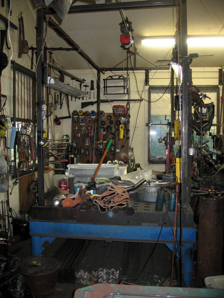
In actual practice this is sort a good news/bad news story.  The good news is it works well.  The bad news is I probably haven’t used it enough to justify building it.  Mostly it has been used as the starting point for building other much smaller framers to aid construction of various projects and it has been handy for hanging things and keeping the clamp assortment organized.  More often it operated in “clutter mode” piled with work in progress.

Selected Dimensions:

End opening between posts = 4’4”
Side opening between posts = 9’4”
Table surface to top frame = 6’2”