Contents

Tuesday, March 29, 2011

Making Concrete Bases


My local scrap yard is perhaps an anachronism. I have heard other blacksmith friends say their scrap yards don't permit wandering and picking because of liability concerns. I have enjoyed this privilege for years and even have an informal "wish list" which they pay attention to and they will lay aside things they know I want as they receive them.

From their perspective the profitable steel scrap is the dense items and flimsy things such as drums and tanks are a nuisance because they must be crushed or cut to compact the density for shipping. Those hollow items I can often pick up free. 30 gallon drums are my favorite and beer kegs are useful too.

In fact the first concrete base I made following the cone mandrel was a beer keg base for my first Peter Wright anvil. I decided how I wanted to attach the base to the feet of the anvil with bolts and incorporated that structure into the base as I filled it with concrete. This base worked nicely and I was encouraged to try it with other tools.

Now the asymmetric vise, small ring roller, and one post vise are mounted on concrete filled 30 gallon drums. A drum is about 18.25" in diameter and 27.5" tall and holds about 3.5 bags of Sakrete. So when the tools if mounted the whole piece will weigh in the neighborhood of 300 pounds.

It has recently occurred to me that it might be wise to incorporate a lifting hookup into the barrel when the concrete is poured. This would allow the chain hoist to lift from the base without pulling directly on the tool.

When I mounted the portable post vise I made sure it was the same height as the main one in the forge room so the two could be used in conjunction. This isn't a common occurrence but occasionally is handy when doing such things as symmetrical reverse twisting or keeping both ends of a bar oriented while doing something to the middle of it.

One final tip for the cost conscious person. When I go to the farm and ranch store where I buy most of my supplies, such as Sakrete, I ask if they have any damaged bags in the warehouse which they was to move. Once they had a pallet which had been bumped by a forklift and I was able to pick up my purchased bags and they threw in all the torn bags free.

A Fabricated Cone Mandrel


In 1997 I fabricated a cone mandrel that is still in use. At the time I hadn't come across a real cone mandrel yet but latter found two good ones. I did have two small cone mandrels. One was long and skinny and the other squat and wide. Both seemed awkward to use in the anvil hardy holes. I wanted a better base, taller and stable and something I could cobble together in a week.

I drew up some plans and took them to a fabrication shop which cut and bumped the halves of the frustrum on their break. I MIG welded them and placed and welded a centered square tube which fitted the mandrel tangs. A circular 4.5" end plate was welded with the center square cut out. This made a watertight hollow form which, when turned upside down, could be filled with concrete. A piece of rebar was place in the central opening and driven into the ground to hold the vertical position. I used Sakrete High Strength Concrete Mix and don't recall the exact amount but I think it just a bit more than one 80 pound bag. The entire volume was concrete filled. The finished base was left in place outdoors for about a week while the concrete set and dried.

The project was finished by welding a circular base plate which aids the smoothness and rapidity of travel when the cone is tipped and rolled into position. I painted it black and put it to work.

This has been one of the most satisfactory tools I have constructed. It has served its' primary purpose as a base for the mini mandrels and the base was used to form larger radius elements until the real cone mandrels were acquired. It cost less than $100 and was quite simple to make. It might not hold up to heavy use especially if it was used for cold work.

This experience led directly to making concrete filled bases for other shop equipment. I'll describe some of those applications in the next post.

Friday, March 25, 2011

Magnetic Pickups


I use this tool a lot. It helps offset the handicap of stiff knees and back and being clumbsy. It seems as if I drop things several times a day which bounce away into some hard to reach place. Fortunately most of those dropped items are steel and can be retrieved with a strong magnet.

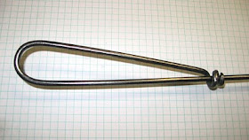
At each of the various work stations I have placed a long shaft magnetic pickup. Here is how they are made. Cut 48" - 60" of 3/16" round. Draw a 1" taper and torch heat a 1.5" segment about 9" from the tip and bend a 180 hairpin with about a 1/2" radius. Then I clamp the bend in the vise and heat about 1.5" of the tip and wrap it around the shaft to form a comfortable handle loop.

On the opposite end I weld a 20d nail and polish the face of the nail with a flap disc. Then I apply a thin layer of Goop adhesivehttp://www.biosafe-inc.com/ag_adhesives.htm to the nail face and a rare earth magnet disc 1/8" x 1/2" is placed followed by another drop of glue and another magnet. When the glue is dried I have a very durable light weight magnetic pickup.

Each magnet has a pickup force of 5.3 pounds so the tool can lift about 10 pounds. A packet of 14 magnets costs about $10 so that will make seven tools for the shop and require about thirty minutes work and it will save a ton of time and awkward bending.

Tuesday, March 22, 2011

Dual Tang Die Carriage


My first power hammer was a 50 pound Little Giant. I took the rebuilding course offered by Harlan "Sid" Suedmeier in Nebraska City, Nebraska. Check out http://www.littlegianthammer.com/.

I added the usual modifications, spring guard, flywheel brake and a die carriage. Originally the die carriage was a single socket off to one one side of the combination die that would accept a 1" square tang. A variety of dies were made which fitted into that retainer, flat texturing dies, stops of thickness from about 14 gauge up to 1.5", and spring dies. It was the spring dies which gave me the most trouble with wobbling and loosening and loss of control and led to adding a second tang socket on the other side of the power hammer die.

I was very impressed with the increased stability and eventually modified all my dies to the new platform. Later I learned to make my own power hammers based on the Ray Clontz style 50 pound spare tire hammer (STPH) idea. The first one followed the set of plans rather closely in most aspects but after some experience with it I built a couple more hammers with wider throats and 75 pound hammer heads.

On the newer hammers I constructed quick release dual tang die retainers. Refer to the diagram and images above. The basic concept is to hold the die in place with just the weight of the square tube sleeves surrounding the post sockets which receive the die tangs. The die is dropped in place and each sleeve is lifted and a forged "T" shaped key slides in over the die and locked with a large cotter pin which is tethered to the key. To change dies I pull the cotter pins and place them in drill holes in the base tabs and slip out the key and just drop it. The tether prevents the keys from getting separated from the system.

This mechanical system restrains the dies rather tightly in front-to-back and side-to-side directions but permits some up and down movement which doesn't seem detrimental and may actually protect the die. In my situation I found that the stop dies don't require dual tangs but all others are designed for two tangs.

I made a jig to hold the tangs in place while welding so I know they will fit the sockets well. Also the tangs which are made from 1" 14 gauge square tube scrap pieces about 1" to 1.5" in length are "tapered" by collapsing the sides on the leading edge of the tang with the cross peen of a forging hammer.

Stamping each die with some alpha-numeric label is one more detail which aids record keeping. Naturally the stops are stamped with their thickness. Others are stamped with something like BT6 for the #6 bottom texture die. My project notes will record exactly which die was used.

Sunday, March 20, 2011

Making Fly Press Tool Tangs


Following up on the theme of making edge tools with tool steel these are some ideas about making the tangs with which they will mount in the fly press.

My fly press is a small one but just right for my purposes - the Goldilocks Principal. The socket in the ram which seats the top tools has a 1" diameter. Depending upon the required finished length of the tool I use either 1" x 1.5" bolts (shorter tools) or 1" thread rod (long tools).

The tang needs to seat as deep as possible to provide the lateral support but it should not be able to bottom out and upset the end of the tang or damage the base of the socket. All the vertical force on the top tool should bear broadly on the face of the ram. When using the thread rod I use a depth gauge made from a piece of tube which fits over the 1" rod. A 1" - 8 nut is screwed down to expose just the right length of tang and then welded in place with the MIG welder.

If I need 60º Indexing, 5/8” - 11 coupler nuts work great as top tangs. Usually the tool fits in only one or two rotational positions so I just grind a flat spot to the depth of the threads so the set screw will have a point to seat nicely in those positions.

The tangs for the base socket are made from 7/8" - 9 nuts if a slightly loose fit is tolerable or a 1" section of 1.5" schedule 40 pipe with a 1/8" slit cut out when a tight fit is required. There are 1/2" slots in the base frame on both sides of the bottom socket so "outrigger" bars can be attached to the bottom tang and extend out to drop into one or both of those slots to securely fix the rotational position of the bottom tool if needed.

When attaching a tool to the top tang, such as was described in the previous post, I allow for a standoff gap and make a single tack which permits me to double check and adjust the orientation before final welding.

It seems important to pay careful attention to the condition of the set screw in the ram. I replaced the original one with a grade 8 bolt and made a custom wrench from a socket wrench with a welded "T"-handle and it hangs on a cord from the stand close at hand. Inspecting the tangs for any fret marks from the screw may show there is undesirable movement of the tang which could damage the screw. If the end of the screw became upset or the end threads damaged it could be very difficult to remove the screw without damaging the threads in the ram. As usual it is easier to prevent a problem than fix one.

Using Tool Steel


Yesterday I forged a slitting chisel and an opening chisel for the fly press for a future project. I chose H-13 tool steel for the job. The only alloys I buy are H-13 and S-7. From time to time there are opportunities to pick up free of charge some used trenching bits for hardy tool blanks or some coil spring or a torsion bar but I don't buy them. Years ago I placed a couple of orders from a major supplier and paid the premium price but in recent years I have always been able to find what I need at a tailgate sale for a very reasonable price.

I picked a 1" round bar of H-13, heated it in the coal forge and forged the shape of each chisel in a single heat on the power hammer. The rest of the work was done with the bench grinder, flap disc and belt sander, silicon carbide wheel and finished with the hard felt wheel dressed with chromium oxide polishing compound.

I welded it to the fly press top tang in proper alignment. I first tacked it in one edge spot with the MIG welder with a short bead which I can bend cold while the tool is in the fly press adjusting it's position before the final welding. When it was finished I heated it up above critical and let it air cool.

The tool steel probably cost $2 and it took about a half hour to complete. The process is really so quick and economical it is reasonable to plan on making exactly the right tool for each job.

That leads to the issue of dedicating tools. I have a number of items I make time and again so it seems easiest to dedicate the small tools, jigs, blanks, etc. and store them together until the next time I need them. If I know the tools will be used infrequently for short runs that leans me toward using my "free" tool steel for the edge tools. Many don't need any heat treatment but occasionally one needs an oil quench to harden enough. For the swage type tools water quenched mild steel works well in most cases.

For completeness I should add that I did buy some 4140 annealed die stock for my Smithin Magician and have made several custom dies. The instructions for heat treating came with the material and are as follows.
Normalizing: Heat to 1600/1650°F (871/899°C), hold for 10 min. and air cool.

Annealing: Heat to 1550/1600°F (843/871°C), pack in lime or wood ashses until cool.

Hardening: Heat to 1550/1600°F (843/871°C), and oil quench.

Tempering: After hardening, heat to a temperature 400°F to 500°F and air cool.
I'm sure that's really useful to anyone who has a heat treating oven but I don't. The dies I've made have enough radius on the edge that hardening hasn't been much of an issue so just heating and oil quenching by guessing has worked OK. Some call that the SWAG method, the educated guess, intuition or just guerrilla metallurgy.

Tuesday, March 15, 2011

Creating a Rust Patina


A sealed rust patina, I find very appealing and it can be especially useful in outdoor applications. I plan to use it on the outdoor sunflower sculpture on which I am currently working.

In this project I have used the usual 14 gauge material to built the hollow formed stem components but they are not yet fully assembled. Up to this point the pieces are less than 5' in length, which is the maximum my tumbler will accommodate.

I decided to go ahead and start the rust patina process and let it work as I studied how to complete the project and to store all the pieces outside which gives me that much more shop working space and lets the weathering work on the patina naturally.

The surface was cleaned with a degreaser such as acetone or lacquer thinner after tumbling. Then I applied muriatic acid (hydrochloric acid) with a chip brush and immediately sprayed the surface with hydrogen peroxide in a plastic spray bottle.

This will usually produce some rust color almost immediately. I'll return to check on the progress every few minutes and probably brush with the acid another time or two over a half hour period. By then the surface usually looks pretty evenly rusted and after that I use only the peroxide spray another couple of times. I leave the pieces outside to weather until they are ready for final assembly.

The last step will be to apply a sealer when the project is finished and the patina is evenly established. I will use fast drying satin polyurethane as the base coat. Several additional coats of the same can be applied or another type of satin sealer which is compatible with it. I have experimented with several finish combinations to find what works for me and what doesn't.

Finding a Niche


When I became interested in blacksmithing and started my first first forging efforts I had no sense of direction to the work. I was only interested in acquiring capability in general. As time went on and I accomplished more work I continued to cast a wide net and attempted to make many different things. Eventually I could make a lot of things but none really well.

This wasn't a bad strategy for a beginner in my situation where there was no living-breathing instructor, only books. Progress depends mostly on practice, anyway, I think. My further experience path was directed by the specific projects which clients requested. Some proved more satisfying than others and I started narrowing the vision of which things I wanted to do and which I didn't. By concentrating on the most interesting types of work I improved my skill in those areas and the overall satisfaction of the creativity increased.

Large architectural work is not for me. I mostly work alone and don't have the strength of youth and endurance necessary for heavy projects. I prefer smaller projects involving natural forms particularly botanical elements. I incorporate many different kinds of them into various sculptural decorations.

Currently I'm working three projects which employ forging and fabricating hollow forming techniques which I have developed over the years and enjoy using. One is a large sunflower sculpture which will hang on the outside west wall of my studio. The second is a large pair of interior doors which present a woodland scene. And the third is three runs of grape vine hand rail. All include stem, trunk and vine elements up to 3" round. Obviously, solid stock can't work in those applications because the weight would be enormous. I have encountered this design problem many times and find the hollow forming an ideal solution. The closed shape lends great strength with little actual mass.

I can briefly describe the process as follows. Mostly I use 14 gauge HRS sheet but sometimes 18 gauge if even lighter weight is required. I request the steel supplier shear the 14 gauge into pieces 2' to 3' in length and about 4" in width. This size is easy to work given the tools I use.

The first step is to run all the sheet through the coal forge to fire scale and anneal. Next I run the stock through the tumbler with steel aggregate for about 20 minutes. This knocks off all the scale and leaves the surface with a very fine pitted and planished texture which will eventually be the "tooth" which holds the finish in place.

The second step is to heat the sheets again in the coal fire and boldly texture the surface with one of a number of bottom dies I have made for the power hammers which produce specific bark patterns.

Next, I use the flypress with a bottom trough die and top ball die to bend the sheet into the desired radius of concavity needed for the fabrication of the final form. If the sheet is 4" wide and the final form is a branch about 1.25" in diameter (4/pi) I can completely close the tube by switching the top ball die to a top trough die. I don't strive to create a symmetrical pipe as some undulation will be desirable in the finished product.

Finally I place the tube in the post vise and close the seam with a MIG weld bead then fuse the seam with the oxy-acetylene torch and run the finished piece through the tumbler again.

The final structure will require some tapers and bends rather than just single diameter tubes. Tapers are formed by cutting the sheets into elongated trapezoids which are then tubed. Bends can be complicated but often require removing and replacing various geometrical areas.

I find this building process fascinating and I am happy that I have found this niche technique. To each his own.

Monday, March 14, 2011

Using Google SketchUp


Another plug for Google? No, I'm not on their payroll. I'm just reporting on what I have found useful - and free. SketchUp http://sketchup.google.com/ is another internet tool which I have been using for a while and I still would not consider myself fully competent or an expert just yet. I used a couple of other much simpler drawing programs for years and I have never used the high-end and pricey ones such as 2D-3D AutoCAD (design, drafting, modeling, architectural drawing, and engineering software) or 3D CAD SolidWorks (3D mechanical CAD) so I can't offer any opinion about how they compare.

SketchUp is described as 3D sketching software for the conceptual phases of design. It is free to download and there is good reference and tutorial instruction supporting it. I found it easy to get started creating and modifying various solid objects but I soon slowed down as I began to learn the finer details which really make the program most useful. I'd say it took me about 40 hours to get as much competence as I needed to put it into every day use.

I recently added the Terry Ross plugins explained in the Winter 2008 issue of the Hammer's Blow. I intended to do it at the time I read the article. Well, time flies. Now it is the 1.2.1 Version - 01-11-2011.

I don't do much scroll work but for those who do the Curve Maker tool should be really useful. It offers these line varieties; Archimedies spiral, Bernouli spiral, Euler Spiral, Cosine Curve, Fermat Spiral, Helix, Hyperbolic spiral, Lituus Spiral, Golden Spiral and Sine Curve.

The Taper Maker is more useful for my day to day use. It is made for square, rectangular, round, hexagon, octagon and diamond stock. The diamond is square rotated 90º, as you would expect. The bevel angle defines the edge break or chamfer.

The Stock Maker handles square, rectangular, round and hexagon stock. The rectangle tool models sheet and plate stock which are just rectangles with little thickness.

The Cost tool is still a mystery to me. It's probably useful on really large projects. I'll explore it more when time allows.

My design work doesn't seem to require more than this free version of Google SketchUp 8. I have a couple of friends who like SolidWorks but I'm not looking to spend any more money on a drawing program until I think I really need it. For years I got along with just pen and paper but I have come to rely more and more on the software drawing programs as their intuitive interface has improved.

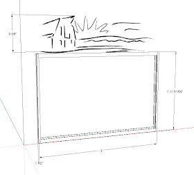
Now SketchUp is my primary design tool. I like the ability to layout 2D and 3D plans with very accurate precision, 1/64" and 1º limits. Also the ability to create a 3D model and orbit it to any point of view is cool. I can rotate the design to front, back, side, Top, Bottom, etc. and print the image. Also, I can capture screen images which can be emailed to a client for comment.

Computer Convenience


I can't really imagine how much more difficult running the business would be without computers. Over the years I built a business plan which is highly dependent upon them and I still see that as a good choice.

I have a good laptop which I keep in the house and it never travels to the studio thus avoiding the grime and other hazards there. In the studio I keep an older, largely out-of-date laptop. Both are internet connected through a wireless hub and both store my currently used files but what really makes this setup work is Google docs.

My older son, introduced me to this powerful tool and I have been using it for some time and find it highly useful. Google docs is reached by opening the Google Home page (http://www.google.com/) and moving across the title bar where it offers Web, Images ...Gmail, more. Scroll down the "more" menu to Documents and you're there.

I needed to setup a free Gmail account by entering a username and a password to setup my personal documents cyberspace. Under the "Create new" menu it offers Document, Presentation, Spreadsheet, Form, Drawing, etc." I have used the Document, Spreadsheet and Drawing tools - most often the Spreadsheet. After my account was set up I was able to begin creating and also uploading files I had already been using. They can be organized into "Collections" or what I think of as folders. I can choose to keep the files private or I can designate certain other people who have Google docs accounts to share access to designated files. This allows working with a collaborator or an editor.

The really handy aspect of this tool is being able to use the same files whether I am in the house or in the studio. If I am working on a job in the studio and want to add notes to the timesheet I know the changes to the Google docs file will be up to date when I check them later at the house. There will never be two even slightly different versions.

Over time I have uploaded my hanging files database, my current client work files, inventory files, materials pricing files, and other frequently used information. The convenience this organizational change has created is really gratifying. It required some time and work and learning anything new can be frustrating at times but, in this case, it was really worth it.