Monday, May 30, 2011

The Pivot/Lock Rod Fuller


Yesterday I needed to make several pieces which I call "pivot/lock rods". They require a pair of opposing fuller marks to demarcate where to begin drawing each end segment on a piece of flat bar. It has been several years since I last made them and don't recall exactly how I it was done as my record keeping wasn't as good back then.

I decided it would be easiest to do on the fly press where I could sit down and get a really good view of of the register of the work piece on the bottom fuller while spinning down the top fuller. The work needs to be rather precise. The only problem was that I hadn't yet made a pair of fullers of the appropriate radius. All the completed ones were larger.

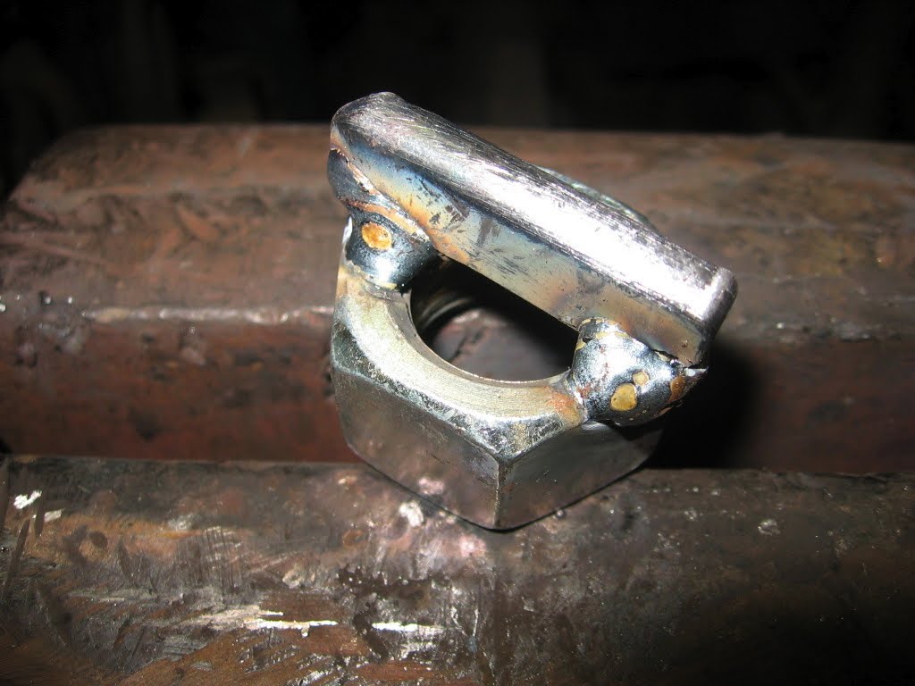
The decision was to go ahead and take the half hour or so which would be required and make this tool. Step one is see in image 01 showing a piece of 5/16" radius H13 tacked to a 7/8" nut which works perfectly as a bottom tang.

Step two is see in image 02 where I selected a 1" x 1.5" bolt as the top tang and welded a short shaft which I measured when I had the bottom tool seated. The top 5/16" radius H13 piece was tacked to the shaft.

I seated the top tool in the socket and tightened the locking nut with the rotation in the position for general use (avoiding obstruction). The end of the nut slightly flattened two of the screw threads on the top tang which were easily seen when I removed it. I used the grinder to cut away those threads so the lock bolt would rest on a flat surface in that location.

Image 03 shows all pieces lined up and tacked with two bottom flanges added to take stress away from the welds between the H13 and the nut.

The final step was to MIG weld all around and add a short handle to the bottom tool to make it easy to rotate into exact alignment with the top tool which is locked.

It did take about 30 minutes to make the tools but it only took a couple of minutes to mark the six work pieces perfectly and the tools will be available for other jobs now.

The Smithing Magician http://www.britishblades.com/forums/showthread.php?17493-Smithing-Magician-Guillotine would be my next best choice for this job. I have it set up for the treadle hammer and the light in that workspace isn't as good as at the fly press and my angle of view is also not as favorable. I could have placed the Smithing Magician in a vise and struck with a hand hammer

Actually there are quite a few ways to skin this cat but mostly I wanted to show a quick way to make fly press dies.

Sunday, May 29, 2011

Making Old Time Black Fasteners


Yesterday I prepared some 5/16 x 2" lag screws and some 1/4" x 1" carriage bolts for my dinner bell sets which have a swing arm bracket/hanger. To match the set they need a somewhat old time appearance. Recently purchased lag screws, machine screws, carriage bolts and other fasteners are commonly galvanized so the color doesn’t match when they are used with traditional black iron elements. I use this method to largely erase the "store-bought" look.

I remove the galvanizing by pickling in hydrochloric acid for aboit 10 minutes then rinse in water. I constructed a special 5 gallon bucket set up to do it. This was described in "The Pickling Bucket" post.

I also made a special Decorative Hardware Vise Tool which allows me to securely hold the threaded fastener in the vise and prevent damage to the threads while I do the finish work on the head. I used two pieces of 1.5" x 1.5" x 3/8" angle about 6" long to make the tool - see the diagram which shows my plan and the image which shows how I actually made it.

Any lettering or symbols on the head of the fastener are removed with a flap disc. The head is then heated with the torch and planished with a light hammer to produce a faceted surface. I try to avoid significantly deforming the perimeter of the heads so the proper wrench will still fit.

While hot, the surface can be brushed and wax applied to achieve the proper black color and protection.

Usually I plan projects to mount with 5/16" or greater diameter hardware but for short lengths I may use 1/4" diameter.

If I had a really big project to do I would probably just order the black, square head screws and bolts from one of the reproduction bolt companies or perhaps forge them from clipped head plow bolts which I can buy and the farm and ranch store.

Thursday, May 26, 2011

Demonstrating at TPNP


On Saturday the 21st of May I did a blacksmithing demonstration at the Tallgrass Prairie National Preserve. Ken and I set up under a walnut tree near the historic stone barn as we have done quite a few times since Heather Brown, Chief of Interpretation and Visitor Services, first asked us to volunteer seven years ago. We try to make everything fit in with the late 1800's period theme when the ranch was young.

These are two links for more information:
http://en.wikipedia.org/wiki/Tallgrass_Prairie_National_Preserve

http://www.kansastravel.org/tallgrassprairie.htm

On Saturday we made a step set to show one way a horseshoe can be made. We started by making two tools, chisel and rectangular pritchel punch, out of S7. Then we made each step from 1/4" x 3/4" x 11" A36 hot rolled stock.

It was the first time I ever made a shoe although I have seen it done quite a few times. We chose to demonstrate the shoe because it was likely farriers who did most of any forging done on the site. I have looked at a lot of the ironwork in the various buildings on the site and concluded that most of it was factory made. Sometimes we forget how widely available this was by the 1870's.

It is fun to visit with the folks who stop by to see what we are doing. They come from all over the world but the majority are from closer cities. I often have a regular visitor who has come several time before.

I can never really anticipate what people may want to see but we have developed a small repertoire of things to suggest; a taper, an upset, a cutoff, a punched hole dropping a slug, a square nail, an S hook, etc. Most visitors know little about coal, iron, the tools, how the fire works and the difference between a blacksmith and a machinist and the history of it all so I enjoy the teaching opportunity.

Over the seasons we have experienced a variety of weather; sunny and windy, cloudy and windy, cold and windy, hot and windy, windy with rain and windy with lots of rain. A nice breeze is something we can depend upon up on the hill where we can see the prairie for miles to the south.

Several women usually cook a wonderful meal demonstrating the historic cooking processes of the time period; open fire, Dutch oven and ranch stove cooking and serve it to the volunteers at noon. We eat outdoors if the weather is nice and in the barn when it is challenging. Other volunteers demonstrate old time methods and crafts and music is a regular feature.

Construction will begin soon on a new visitors center so I won't be doing any more blacksmithing demonstrations this year and I may not continue next year anyway because the setup and takedown gets a bit harder each year and takes a day longer to work out the stiffness.

I am working to secure another blacksmithing demonstrator for next year and beyond. I have one younger friend who seems interested and has worked in the past at a National Park Service site. I'll keep my fingers crossed.

Imperfect Perfection

Yesterday and today I managed to make a supply of Conestoga Wagon wing nuts. They are used on a swing arm hanger for a triangle dinner bell set which is a proprietary Item I designed and we sell them on a regular basis. I'll soon post the instructions for how I make them. Because there is efficiency in dedicating a block of time and making, say, 50 of them in one run I did just that. That's enough for 25 sets so I won't have to go down that path again for a while. Creating a successful product is a bittersweet thing for me. On the one hand, I feel rewarded when the client votes with their wallet and buys my creation. On the other hand, when I make another version of the thing there isn't the same satisfaction of discovery. Novelty is a fire which dies quickly. By the time I've made 25 of them I'm looking forward to doing something else. It is my intention to form them fairly close to identical but to look obviously hand made. There is always a small range of variation nevertheless. While I was working on them I recalled a story told by a farrier at a BAM (Blacksmiths Association of Missouri) meeting a few years back. He said when he was learning the trade he visited a number of successful farriers to observe their techniques and looked through their scrap pile to find examples of shoes discarded because of some defect. At this particular shop there was no such pile. It seemed improbable that the craftsman never made a mistake so he enquired about it. The answer was that, of course, there are, from time to time, some shoes which are just a bit off and don't pair up well. But rather than discard them they are accumulated and ever so often sorted. The various errors tend to cancel out and most can be matched to make an acceptable pair. It works the same way with these wing nuts. Rather than try to make them identical I just plan to pair up the variations. 

Wednesday, May 25, 2011

Storage Jars


To a certain extent I've learned to buy food to get the container. Fortunately I like peanut butter as it comes in my favorite storage jar.

The transparent jar is probably made from polyethylene terephthalate, PET, a thermoplastic polymer resin of the polyester family. The cap is made from polypropylene. It is possible to order them empty in bulk lots if one desired to acquire a lot at once. My collection has grown at a steady, slow, natural, P&J sandwich eating pace for several years.

Standard operating procedure for use in the studio involves drilling two, 1/4" holes approximately 1/2" both sides of the lid center, passing a cable tie through, and hanging it up for later use. When the need arrises I add the contents and label with a correction pen. If the jars use changes later the labeling can easily be removed with lacquer thinner.

Jars which contain something I seldom need are hung on the loft ceiling. I snapped a chalk line grid on the osb board and labeled each intersection with an alphanumeric designation and placed screw hooks at those points. I use a correction pen marker to label the lid of each jar with the corresponding hook number so it is easy to return it to it's proper home, For instance, when I'm looking for the micrometer, I can check the inventory on the computer and find that it is hanging at hook A11.

If the jar contains something which is prone to damage by excess humidity I put a Tyvek Dessicant packet inside too.

My parents behavior was deeply affected by the hard times associated with the Great Railroad Strike of the 1920's and the Great Depression of the 1930's. We saved, jars, cans, string, wire, paper bags and other things. I straightened nails bent when something was demolished. Home made was the best in almost every case. It's in my nature to look for things to save put to good use and it predated the reduce, reuse, recycle axioms of the environmental movement.

Monday, May 23, 2011

The Prairie Pastimes Gallery


A couple of weeks ago Persimmon Forge joined a cooperative gallery in Cottonwood Falls, Kansas - Prairie PastTimes Antiques & Crafts.
http://www.prairiepasttimes.com/
(If you type the URL be sure to note the double t).
also
http://www.cottonwoodfallskansas.com/about/shopping/prairiepasttimes.html - is another reference about the opening event.

The theme is Made in the Flint Hills. Approximately 30 art/craft persons are represented.

Prior to my association their rack card listed these items:
Antique Furniture Antique Accessories
American Girl and Barbie Doll Clothing
Hand-made Jewelry
Embellished clothing for women/girls
Art Furniture & Hand-crafted Silver
Hand-crafted Furniture
Hand-made Picture Frames
Home-made Jams and Jellies & Mixes
Baby Items & Toys
Hand-blown Glass
Stained Glass Decor
Hand-made Pottery
Fabric Kitchen Accessories
New Furniture of Reclaimed Lumber
Antique Music Instruments
Hand-crafted Wood Cutouts
Homemade Soaps & Candies
Decorative Painting
Quilts & Coverlets & TableCovers
Amusing Gift Items
Year-round Christmas Corner
Dancing
Music
Lectures
Crafts Classes

I also saw some fine photography and now I've added some ironwork so the diversity of the presentation is extensive.

The gallery is housed in a historic stone building in downtown Cottonwood Falls, Kansas at 220 1/2 Broadway St . Partners “work the store” on a rotating basis and stock, refresh displays, and do other “housekeeping chores”. To learn more about Prairie PastTimes, contact Sue Smith (620) 273-6003

prairie-maid@sbcglobal.net.


http://www.persimmonforge.com/

Friday, May 20, 2011

Directions to Persimmon Forge


Usually, I welcome visitors to the studio to take the tour or discuss work. It is best to call and make sure I'm not away running errands or working somewhere else. Most of the coal forge hot work occurs between 2 and 4 in the afternoon. That time is noisy and busy and doesn't accommodate conversation well. Still, that is the best time to see how forging is done. Other quieter times are better for just looking around or discussing a project. Currently, I often work weekends and I can open up in the evening if an appointment is made.

From 335 Turnpike Toll Booth, Exit 127:

Proceed toward Kansas City and Industrial road. Exit at 128, Industrial (stoplight). Turn left, north, and continue past the commercial area to 24th street (stop sign). Turn right, east, and continue to Prairie Street (stop sign). Turn left and go one block then turn right onto Coronado. In one block turn left onto Monterey and proceed north and east about four blocks to the second street on the left which is Hacienda Court.

From West Highway 50

Go east on Highway 50 to the roundabout and take the second exit toward Kansas City and Industrial road. Exit at 128, Industrial (stoplight). Turn left, north, and continue past the commercial area to 24th street (stop sign). Turn right, east, and continue to Prairie Street (stop sign). Turn left and go one block and turn right onto Coronado. In one block turn left onto Monterey. Wind north and east about four blocks to the second street on the left which is Hacienda Court.

From I-35 Merchant Street, Exit 130:

Go south on Merchant and right onto 18th Street. Go west to the stop sign at Rural St. Continue west about 10 blocks to the dead end at Maplewood Cemetery. Turn right, north, onto Lincoln St. and go about 3/4th mile through an underpass at I-35. One block beyond it turn left onto Coronado. Take the first right onto Rio Vista which proceeds north and west about five blocks. Turn right at your second opportunity which is Hacienda Court.

Our home is situated on Hacienda Court and the studio is a separate structure closer to the cul de sac on Derecho Court to the east.

Wednesday, May 18, 2011

The Hot Scale Shields:


One of the final additions was front and back hot scale shields, The primary function was to protect the components below from damage from hot metal. The secondary function was to form a shelf for tools and dies and work in progress. In actual use the shelf has been the more useful feature and I may make some modifications to enhance that aspect.

There have been a couple of occasions when a yellow-hot piece of significant mass escaped and bounced down to get stuck down in the vital parts below. Fortunately nothing like this had ever come to rest on a high pressure hydraulic hose where a burn through could be a big problem. I will continue considering a second tier expanded metal or hail screen barrier just above the motor and pump.

Putting it all together:

It was exciting for me to do the first trial runs. I hate to admit it but it is always somewhat surprising and thrilling that another one of my steps off into the unknown hasn't plunged me into the abyss.

Next Time Around:

It's late enough in the game that I don't say that any more. But! If I were going to try another experiment I might try making a version of the "H" frame which had a removable/replacable frame segment which could offer the deeper throat of the "C" style when the need arose.

I might even try shielding the high pressure hydraulic hose with steel or aluminum flexible conduit. It is expensive, by my standards, and It may take some sleuthing to find large enough diameter stock. I believe it is manufactured at least to 4" diameter. In the final analysis, vigilance may be the best policy.

The Reservoir:


I made this one the hard way with each rectangle a separate piece. Long, time consuming, weld seams were required. It was made from 7 gauge scrap which I had on hand. It's probably nearly bullet proof for puncture but a much cheaper version could be cut from a pattern and formed with a break to reduce the welding a lot. Probably 14 gauge would actually have been thick enough in my studio.

This was built on the table top and fitted into a base bracket and secured at the top with two bolts. This quick removal/replacement was designed to accommodate leak repair and it proved handy immediately as a small leak was found shortly after initial testing.

I got a lot of advice on the desirable reservoir capacity. I ended up making a tank with over 10 gallon volume and I think this is over done. I understand that a large volume is favorable for keeping the fluid cool but I operate my press with long intermissions so I don't think heat buildup would ever be a problem with a reservoir half the size. Also, I would position it so that there was no obstruction to the working area. That would occur automatically if a "C" frame design was built.

The Foot Treadle & Linkage:


This mechanism could also be built on the welding table and moved to the base when complete. I rarely use the hand control on the valve in favor of the foot pedal as both my hands are usually occupied holding work pieces and tools. It took a little tweaking to get the right amount of slop in the joint between the rod and the tab on the treadle shaft to make it work smoothly.

Pressure Gauge and Toggle Switch

The Switch
The Pressure Gauge
What is this for? It doesn't cost much and I couldn't tell if it was a necessity or a bell/whistle so I have one. I suppose if one desires to do tweeking experiments to power-up the system this would be the yardstick but I'm not going to do that. My machine works fine for what I want to do and I say, "never trouble trouble till trouble troubles you."

On my power hammers I have have used Square D boxes with fuses but my electrical advisor suggested I try a circuit breaker type on this machine. What can I say? It works just fine like the other type did.

Hydraulic Hose Plumbing:


I didn't know much about any kind of plumbing. I don't think I was paying much attention in the fluid mechanics part of my physics class 50 years ago and haven't needed to use any of it until lately. I quickly learned that black pipe and it's fittings are cheaper than equivalent diameter hydraulic hose and fittings and they seem to be used pretty much interchangeably.

The farm supply had a rather limited selection of hydraulic components and I might have been better off having custom hose assemblies built by another company which does custom work but I opted for off-the-shelf stuff. It came in one foot length increments from 2' to 5'. There were male fitting on both ends.

I got free conflicting advice on whether 1/2" hydraulic hose or 3/4" hose would make a noticeable difference. As it turned out I had to use some of both because that's all the store had at the time. High pressure hose isn't needed on the return line from the control valve to the reservoir or the "suction" line from the reservoir to the pump, as I understand it, but I'm not keen on hose clamps. They look tacky and the high pressure hose seems to just dress everything up and make it look more expensive, which it is.

The Power Platform - Motor and Pump


The mounting plate is 1/4" x 8" x 21". On the table top a Dayton 1TMX8A ,3 horsepower, single phase, 230 volt, 40 Amp, 1740 RPM motor was mounted in line with the Haldex ,11 GPM log splitter, open center, pump and joined with a Lovejoy type coupler to accommodate the shaft diameter disparity.

When the assembly was completed it was mounted, welding the three elevator struts to the base plate.

With motor and switch in place I could determine the length of 10-3 service cable needed to reach from motor to switch - about three feet. The left over 12 feet were wired to a 230v plug matching my nearest outlet. Smaller cable might have been OK - I'm not an electrical authority. I suppose less resistance is usually better. The hefty cord looks professional and the yellow color makes it easy to see and protect.

Cylinder, Filter & Fluid


Cylinder:

The base clevis fitting was done when adding the bottom web bolsters to the frame. Now the clevis of the shaft end of the cylinder was carefully fitted to the base of the ram. Two 5/8" bolts pass through the ram faces and core and hold the assembly together in the frame. The hydraulic cylinder mounting was then completed.

The Filter:

After studying several internet sites with technical data about hydraulic fluid filters I confirmed again that a person can easily overdo on information. How important is it to understand the difference between a return line filter (low pressure) and a supply line (high pressure) filter? What about the micron size - 10 or 20? One friend told me he ran the machine he built for 30 years without a filter.

Hydraulic Fluid:

What kind and how much? I bought 10 gallons of Mag 1 R&O ISO 68. I kept and stored the containers the fluid came in in case I need to drain it all out some day and keep it clean.

The Dies:


Some time in the obscure past I acquired some odd 50 pound dies and used them to make top and bottom flat dies on "U" brackets. I figured I would fit other quick-fit custom dies over them with saddle mounts. This has worked fine so far. If I had a long run of some particular thing I would probably remove the bolted flat dies and replace them with other custom bolted dies.

The images show what I cobbled together. The bottom die is a KDS lower base turned upside down.

The Ram:


Back on the welding table again. I had a supply of 1/4" x 3" scrap brass flat bar so I used some of it to make guides which, optimistically, would reduce ram friction when heavily greased. When all the ram parts were cut and fitted I glued the brass to the ram faces and welded short keepers above and below to hold the brass in place under load.

Frame - Part 2:


Heavy Frame Reinforcements:

I waited until working with the frame moved to the floor to add the top plate and the top corner straps as well as the vertical side flange bolsters, reservoir support bracket, reservoir bolting tabs, control valve mounting flange and Square D switch box. If I had a heavy duty overhead hoist I could have done all that comfortably on the table.

Frame - Part 1:


The Web Cutout:

On the table I cut out the web window for the operational area using a torch guide jig then cleaned both side edges with grinding discs.

A torch cutting guide can be made by tacking together some scrap such as 1” square tube. The opening measured about 8.25” x 40” and was started 5” below the top and ended 10” above the bottom of the beam. This leaves a web remnant a bit over 3" on each side in the ram operating area. I cleaned the faces of the web remnants with 120 grit abrasive flap discs for a smooth slide of the greased brass guides which would be fitted later. Tis arrangement has worked very smoothly without any chatter.

Lesser Frame Reinforcements:

While still on the welding table I added the top front and back web bolsters and the bottom front and back web bolsters with the appropriate clevis cutouts. Also I did the final fitting of the cylinder base end clevis yoke, drilled the clevis pin hole and welded shims as needed.

The Press Base:


If I had intended for the base to be fixed to the floor with concrete anchors I would have drilled or torch-cut corner holes while on the table top. On the front side two holes can be placed without much concern with obstruction. On the back side the mounting plate for the motor and pump could be an obstruction problem for hole making at a later stage.

I placed the base plate on heavy pipe rollers to ease moving during construction and later removed the pipes. Probably I should have made some clever fittings which would aid raising the front and back edges of the plate to the height of my roller pipes to make moving easier in the future.

There doesn't seem to me to be any advantage in anchoring the base to the floor. My machine has never tended to vibrate or walk around.

Persimmon Forge Hydraulic Forging Press - Introduction


This forging press was built after considerable research and planning and I use it every day and I am quite happy with it's operation. Like most other machines it's construction process and it's operation is inherently dangerous and requires considerable skill to mitigate risk. This information is made available as an explanation of "how I did it" and is not intended to be a recommendation to others. It is offered without charge but if anyone finds such information useful and wants to send me a few bucks to keep me encouraged about making this sort of post - Super!

This is first installment of a series describing the construction of my press.

I chose the "H" frame and cylinder-below-ram designs for strength and to keep the overall height to a minimum decreasing the amount of steel I needed to purchase for the frame.

The size of the I-beam frame was determined by what I was able to find in a stack of drops at a local engineering company. If I could have located a wider web beam at the time I probably would have used it to increase the working space.

The construction got heavy fast so I found it desirable to do as much work at table top height in subassemblies as possible before moving to the floor. Knee pads helped when working on the floor.

Monday, May 16, 2011

Storing Tool Steel


Years ago I collected coil springs at the scrap yard for a supply of tool steel to make some punches and drifts. The springs ranged from 1/4" round stock to about 3/4". Thinking they would be less bulky to store I heated them up, straightened them and shelved them annealed for later use. I didn't foresee the risk of losing track of what was tool steel and what was mild steel and eventually a piece of coil spring made its' way into a round stock cold shear and broke a blade.

That shear was one most handy tools I ever bought so I contacted the maker, Don Nichols, the same friend I mentioned who gave me some tips on the hydraulic forging press. He made another one for me so I'm back in business. It easily shears cold stock up to 3/8" round.

The blades are mounted in a bypass design so the sheared surface is transverse to the long axis just as a band saw cut would be. This type of cut is the most desirable if the end is to be finished flat but a slight disadvantaged if it will end in a taper.

Today I store coil springs "as is" so there is no ambiguity about their identity. The same applies to grader blade, flat spring, plow discs, hay rakes and harrow tines. I use the correction pen marker to write, 5160, S7, H13, or 4340 on the stock if I know the alloy identity.

In the early days I had nearly free access to it and accumulated more scrap tool steel than I could ever use. Sadly, that scrap yard seems to be closing but that's another story. Still, at this point in time I really need to divest myself of some of the pile, or as the old timers say, get shed of it.